First, the boring stuff. It's in the Cisco docs, however I will add it here.
Add APs to a Map
This procedure describes how to add APs to a map.
Make sure that you have Cisco APs in your inventory. If not, discover them using the Discovery feature.
Step 1 Click the "hamburger" menu icon and choose Design > Network Hierarchy.
Step 2 From the left hierarchy tree, choose a floor.
Step 3 From the map toolbar, click 2D > Add/Edit > APs.
Step 4 In the map left pane, click Add APs.
In the Add APs slide-in pane, do the following:
⦁ To add an AP: Click Add next to an AP that you want to add.
After adding the APs to a floor, close the Add APs window.
When you add an AP to a map, the wireless map automatically stores the following data even after the AP is deleted from the inventory:
⦁ AP name
⦁ AP MAC address
⦁ Current site of the AP
⦁ Current position of the AP on the map
Important: When you delete the wireless controller with all its managed APs from the inventory, Cisco DNA Center displays a planned AP icon for the corresponding APs on the map.
Important: If the same AP is rediscovered in the inventory later, Cisco DNA Center automatically places it back on the map at the same site and position even if a different wireless controller manages it.
To remove the AP data from the map when the AP is deleted from the inventory, you can do one of the following:
• Before deleting the wireless controller from the inventory, assign the corresponding APs to the Global site.
• After deleting the wireless controller from the inventory, remove the corresponding planned APs from the map.
Add Planned APs to a Map
Planned access points will likely be pre-loaded onto new floor plans before the migration. Adding Planned Access Points (PAPs) should not be necessary. If modifications are needed, continue with the following configuration.
After you install the actual APs in the wireless network, you can assign them to the planned APs on your map. This procedure describes how to assign planned APs to actual APs.
Step 1 Click the "hamburger" menu icon and choose Design > Network Hierarchy.
Step 2 From the left hierarchy tree, choose a floor.
Step 3 In the map toolbar, click 2D > Add/Edit > APs.
Step 4 In the left pane of the map, in the AP Models area, click the AP model of the planned AP to add.
This procedure shows you how to use the AP Model Catalog feature to add a planned AP to a floor and configure its model, antenna type, azimuth, and elevation orientation.
Step 5 On the floor map, click the location where you want to place the planned AP.
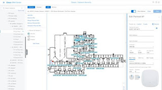
Step 6 In the Edit Planned AP slide-in pane, click the gear icon that is located next to the AP Name field.
Step 7 When you add the first AP to the floor, make sure that you enter a valid name pattern, for example, jkn001-011-ap01.
Important: The planned APs must be unique within Cisco DNA Center. So, make sure that the name pattern identifies the floor. Access points imported from Cisco Prime can NOT have the same AP name.
Step 8 From the Antenna drop-down list, choose the appropriate antenna type, including dual antennas, for the AP.
Step 9 Depending on the antenna type, enter the Azimuth and Elevation orientation, in degrees.
Step 10 Perform the following actions, as needed:
• To add another planned AP with the same properties as that of the planned AP that you just added, on the floor map, click a location where you want to position the new AP.
A new AP icon is displayed on the map with all of the properties inherited and the AP name appended, for example, jkn001-011-ap02.
• To add more planned APs with the same properties and appended AP name, click the floor map.
• To stop adding planned APs to the floor map, press Esc or right-click the floor map.
• To reposition the planned APs, drag and drop them to the appropriate location in the floor map.
• To delete a planned AP, right-click the AP icon and click Delete.
• To edit a planned AP, right-click the AP icon and click Edit.
Step 11 In the map toolbar, click Save.
Assign Actual APs to Planned APs
After you install the actual APs in the wireless network, you can assign them to the planned APs on your map.
Step 1 Click the "hamburger" menu icon and choose Design > Network Hierarchy.
Step 2 From the left hierarchy tree, choose a floor.
Step 3 In the map toolbar, click 2D > Add/Edit > APs.
Step 4 In the left pane of the map, click Assign PAPs.
Step 5 On the floor map, click a planned AP.
Step 6 In the Assign Planned APs slide-in pane, check the check box next to the AP that you want to assign.
Step 7 Click Assign.
Step 8 In the map toolbar, click Save.
Position an AP on a Map
After adding APs to a floor, you must position them on the map if they were not imported by a Wireless Architect using a design tool.
Step 1 Click the "hamburger" menu icon and choose Design > Network Hierarchy.
Step 2 From the left hierarchy tree, choose a floor.
Step 3 In the map toolbar, click 2D > Add/Edit > APs.
Step 4 From the Un-positioned category in the left pane of the map, click an AP.
Step 5 To position the AP:
Click the location on the floor map where you want to position the AP.
Step 6 In the map toolbar, click Save
Edit an AP
This procedure shows you how to change the configuration of an AP.
Step 1 Click the "hamburger" menu icon and choose Design > Network Hierarchy.
Step 2 From the left hierarchy tree, choose a floor.
Step 3 For 2D, do the following:
a) In the map toolbar, click 2D > Add/Edit.
b) On the map, right-click the AP and choose Edit.
Step 4 For 3D, do the following:
a) In the map toolbar, click 3D > Add/Edit.
b) On the map, right-click the AP and choose Details.
Step 5 In the Edit AP slide-in pane, change any of the following AP settings, as needed:
• AP Name or Planned AP Name: jkn001-011-ap12
• MAC Address: MAC address of the selected AP.
• AP Model: Model of the selected AP. Usually 9166 series.
• X-axis coordinate of the AP.
• Y-axis coordinate of the AP.
• AP Height: Height of the AP. Usually 10 – 14 feet.
• Antenna: Antenna type for this AP.
• Azimuth: For omnidirectional antennas, the azimuth is not relevant if the elevation is 0.
• Elevation: in degrees. You can manually enter the value or use the blue arrow under the field to change the value.
Edit Multiple APs
When you select multiple APs, only some attributes are editable, as follows:
• When the selected devices have the same value for an attribute, the value is displayed. Otherwise, the value is blank. In either case, if you change the value, the new value is applied to all the selected devices.
• When the selected APs have the same model number and radios (number of radios and operating band), the antennas are editable. Otherwise, they are not editable.
• You can change the model numbers of planned APs, but not added APs. So, if you select an AP, the model number is not editable.
• Because bulk changes affect more devices, they do not take effect immediately. You must click Apply to apply your changes.
* This procedure shows you how to update the editable attributes for multiple APs at the same time.
Step 1 Click the "hamburger" menu icon and choose Design > Network Hierarchy.
Step 2 From the left hierarchy tree, choose a floor.
Step 3 Do one of the following:
• For 2D, in the map toolbar, click 2D > Add/Edit.
• For 3D, in the map toolbar, click 3D > Add/Edit.
Step 4 Select the APs, using one of the following methods:
• Click the first device, then press and hold the Shift key while you click the rest of the devices.
• In the map navigation toolbar, click Select by rectangle. Then click an area of the map and drag the highlighted rectangle to select APs in a contiguous area. All the highlighted APs within the rectangle are selected.
To deselect APs, use one of the following methods:
• To deselect a single AP, press and hold the Shift key while you click the AP.
• To deselect all APs except one, click the AP you want to remain selected. All others are deselected.
• To deselect all APs, press the ESC key or close the Edit pane.
Step 5 In the Edit AP slide-in pane, configure the settings, as available:
• AP Name or Planned AP Name: Name of the AP.
• MAC Address: MAC address of the selected AP.
• AP Model: Model of the selected AP.
• X-axis coordinate of the AP. You can manually enter the value.
• Y-axis coordinate of the AP. You can manually enter the value.
• AP Height: Height of the AP. You can manually enter the value.
• Antenna: Antenna type for this AP.
Note For external APs, you must select an antenna, or the AP will not be present in the map.
• Azimuth: Angle of the antenna, measured relative to the x axis, clockwise. The azimuth range is from 0 through 360. In Cisco DNA Center, pointing right is 0 degrees or 360 degrees; pointing down is 90 degrees.
You can manually enter the value or use the blue arrow under the field to change the value.
• Elevation: in degrees. You can manually enter the value or use the blue arrow under the field to change the value.
The Cisco 9166i is designed to be placed on a ceiling. 0 elevation means pointing down. For External APs and antenna models that are designed to be placed on a wall, 0 elevation means pointing horizontally and negative values means pointing down.
Step 6 In the map toolbar, click Save.
Remove APs from a Map
This procedure shows you how to remove APs and planned APs (PAPs) from a map.
Step 1 Click the "hamburger" menu icon and choose Design > Network Hierarchy.
Step 2 From the left hierarchy tree, choose a floor.
Step 3 In the map toolbar, click 2D > Add/Edit.
Step 4 To remove APs (including planned APs), do the following:
a) Click the AP, or to select multiple APs, click the first AP and while pressing the Shift key, click the rest of the APs.
b) In the Edit pane, click Remove Selected.
Step 5 In the map toolbar, click Save.
Now for the good stuff.
You likely have Cisco Prime, but maybe you don't. The export feature in Prime exports all the maps and then you import them into DNAC.
If you have the imported floor plans from Cisco Prime into DNAC and try to update the floor plans with a file from Ekahau, your results may vary. If the Building/Floor in DNAC is the same as the Ekahau file, the Ekahau file replaces the floor plans in DNAC and as long as the Ekahau PAPs are named identically, they will take their place on the floor plan.
If the floor plans are not named the same – for instance, the Cisco Prime export has wonky naming conventions and this is the time to fix it, it will upload a parallel set of floor plans. However, they PAPs will not show up on the floor plans, since those AP names exist on another set of floor plans in DNAC.
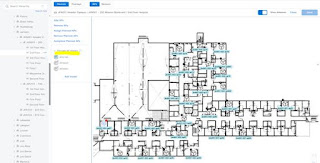
Floor Plans that were imported from Cisco Prime.
There are many caveats with Cisco DNA Center when dealing with legacy controllers and access points.
Mainly, the planned APs must be unique within Cisco DNA Center. So, make sure that the name pattern identifies the site code, floor/IDF, and AP number. Per Cisco documentation:
The planned AP name and the name of the AP that may have been imported cannot be the same name and same case. They can be the same name and different case, however. Specifically, the imported AP can be all uppercase, and the new planned AP and staged AP can be all lower case.+
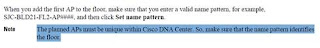
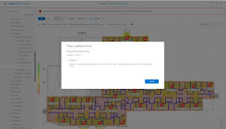
If you try to add a planned AP to a floor plan that was imported from Cisco Prime, you will get the following error:
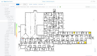
If the newly updated floor plans with PAPs are imported and have all lowercase names in DNAC, they will not show up on the floor plans if there are any access points with the same name and case in DNAC from the imported Cisco Prime migration.
The example below has a newly updated floor with Planned Access Points (PAPs) on it. They are all lowercase names, and four of the imported PAPs did not show up. That is because the Cisco Prime import has mostly uppercase AP names, but does have four lower case AP names. Likely due to some maintenance or other issue and the access points were either renamed or replaced with lower case.
Importing a new floor plan with lower case AP names and having a Cisco Prime import with lower names will not work. A workaround might be to log in to the legacy AirOS controller and rename all of the legacy access points with all UPPERCASE names, such as AUB001-001-AP01. That would allow a new floor plans to be uploaded with all lowercase AP names so that new AP names with lowercase could be added.
Note: Renaming an AirOS access point requires a reboot. Therefore take that into consideration before, should you decide to rename all legacy access points to upper case so that newly refreshed floor plans and PAPs can be uploaded into DNAC.
Floor Plans that were imported from Cisco Prime implementation example:
Step 1. In this scenario, a fresh floor plan with planned access points (PAPs) on it was imported into DNAC. This replaced the legacy floor plan that was imported with Prime, and the legacy APs were added as well.
The access points from Cisco Prime immediately took the place of the planned APs that were uploaded into DNAC.
There are two PAPs in this example that are not being occupied by a legacy access point, since they are likely offline.
Step 2. Import a fresh floor plan with standard naming conventions moving forward. Naming conventions are 1st Floor Hospital, 2nd Floor Hospital, etc. Replacing the floors when spelled out alphabetically.
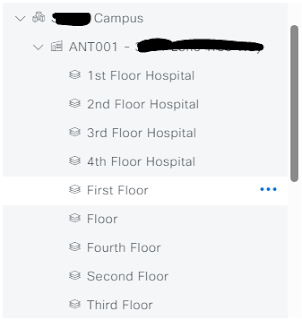
When new buildings/floors are imported, the old floors with the access points that were imported from Prime are still visible. This is because the naming convention is different. "First Floor" does not equal "1st Floor" in Cisco DNAC. They are two different entities.
When the new naming convention/updated floor plans with PAPs are uploaded into DNAC, the planned access points do not show up. This is because Cisco DNAC cannot have two APs with the same name in the system at the same time.
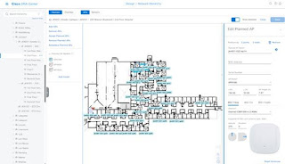
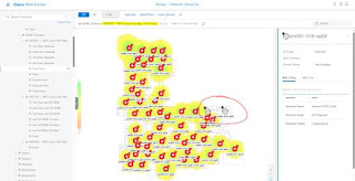
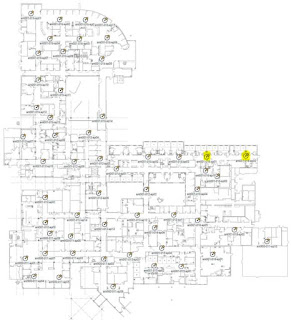
In this example, this is the actual Ekahau PAP floor plan that was imported into DNAC. This is not a screenshot from Cisco DNAC. Highlighted are two PAPs that do not exist in the system, likely due to them being offline – since they are legacy APs that exist.
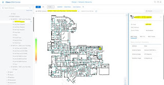
This is an example of what happens when the above PAP floor plan is uploaded into DNAC. When the legacy access points are the same name as the future APs, the PAPs do not show up on the new floor plan. This is because we cannot have the same name twice due to restrictions clearly documented in the Cisco DNAC configuration guide.
I hope this helps someone who might be trying to wrap their head around refreshing ancient Cisco controllers and Prime with new controllers, new APs, and a shiny new DNAC. My advice is to not import Cisco Prime into DNAC if proper housekeeping has not been in order for the last ten years of Cisco Prime care and feeding. Start fresh – new floor plans, Ekahau files with PAPs on them and clean out all those old SSIDs the legacy gear while you're at it.