Saturday, April 26, 2014

High Density Wi-Fi on a Cisco Controller

This blog post applies to those of you who wish to deploy High Density Wi-Fi in your environment.  This is not meant to replace "professional services" – if you are a large sports venue with 75,000 seats, this blog post is not for you.  If you are a smaller environment – such as K-12, University or other college and wish to take a stab at it yourself, please continue reading.

Many of these ideas have been gleaned from the plethora of HD Wi-Fi deployment guides freely available to you on the Internet; Aerohive, Aruba and Cisco to name a few.  I'm going to be using Cisco gear for this post, however please be aware that almost every vendor I know of has an HD Wi-Fi guide and they all say about the same thing.  I'm not taking sides at all – I love all the competition out there!  I would also like to thank a little birdie for sending me a controller for the purpose of this post.

I am under the assumption you know something about how to build an enterprise network, and have deployed an enterprise class wireless network in the past, or had it done for you via professional services and you feel confident in your abilities and want to make your wireless network better.  You should probably have the skill level of a CCNA and CWNA.  I'm focusing on the wireless part – not the backend which will also need to be designed properly.  So, here goes…

The goal is to have smaller cell sizes in the 2.4 GHz range.  This enables faster communication due to higher data rates.  Higher gain directional antennas create small cells and reduce co-channel interference.  More cells equal more throughput, which means more capacity.  More capacity equals happy people. 

One thing to consider if you are designing for your public environment is how many SSIDs you might need.  You many need WLANs for the following groups of users:

a.      Ticketing (scanning tickets to enter the venue)
b.      Point of Sale (textbooks, t-shirts, hot dogs, etc)
c.       Administrative (employee access)
d.      Press (as annoying as they are, they still need access)
e.      Inventory
f.        Dual WLANs separated by frequency (a 2.4 GHz and a 5.x GHz WLAN for             the same purpose)
g.      VoWi-Fi

When designing your WLAN, it is important to have accurate floor plans.  They will help you visualize where your clients will be, where your RF will be, and where you don't want your RF to be.  Place close attention to that last sentence!

The 2.4 GHz spectrum is full.  There are so many devices in there, both 802.11 based and not, that it is difficult for these devices not to be stomping all over each other.  802.11 is a polite protocol – if an AP is on channel one and it hears another AP or client on that channel, the AP will wait until channel one is clear before transmitting.  Adding access points to a large auditorium with omnidirectional antennas does not necessarily increase throughput or the number of users that can be online if many of the access points are on the same channel and can hear each other.

Designing an HD WLAN can be difficult.  There are methodologies that are in place that most of the WLAN vendors all agree upon – so I intend to share them with you since I have read through most of the HD Wi-FI guides out there.  Here are a few that seem to be pretty common goals and methods:

a.      HD Wi-Fi is designed to minimize the cell size
b.      Antenna placement – don't avoid a difficult antenna location because of                  cost
c.       Design more APs than needed and turn off some 2.4 GHz radios if   
          necessary
d.      Use directional antennas in HD open environments – auditoriums, arenas,             conference centers
e.      Omnidirectional antennas may be used in regular, non-HD Wi-Fi areas – as          long as they are enclosed
f.        You're going to have to get creative with hiding APs and antennas in non-               conventional places

As example, let's use this seating chart of a 16,000 seat basketball arena.

This is a large, open air environment.  We'll aim for 250-500 seats per access point.
If you put three dozen dual band access points with omnidirectional antennas in there, you might find that the Wi-Fi doesn't work that well, even though "the math works out".  Your channel utilization will be excessive – I'll talk more about that later.

However, if you were able to mount APs in the ceiling structure (roughly 50 feet above the seats) with 30 degree beam width antennas aiming down at the seating areas (imagine each one of those colored seating areas as a cell) you might find that co-channel interference (CCI) was reduced drastically.  Notice I stated "from the ceiling structure above", and not "from behind the seating area".  The reasoning behind this is that when your venue is full of people, the signal is attenuated more when the antennas are behind the seating areas.  I've seen APs talk to clients at 93 feet when the antennas are behind the seating area – however it didn't work that well.

The other issue with CCI is that signals come from your non-bowl/arena access points.  You've changed out all those omnidirectional antennas for directional ones, but the signal still leaks in from the lobby and concourse areas.  The key here is to use patch antennas in those areas, aiming away from the seating area.  The more "directionally contained" your signals are, the less CCI you will have.

Keep in mind that there's other Wi-Fi out there.  You might have Wi-Fi in the parking lot outside your facility for the hot dog vendors, ticketing, etc.  The best thing to do here is to use directional antennas when possible to minimize CCI.  At least in those areas you won't have as many users as you might have inside the seating area of your basketball arena. 

Other Wi-Fi exists that you might overlook.  Moveable partitions slide to the side and open up your environment, changing the dynamics of your RF propagation.  Glass walls in arena suites slide open and let RF spill out into a seating area if you are using an omnidirectional antenna.  I cannot stress enough the need to properly survey your area and to use patch/directional antennas!

We're going to start to dive into some of the nuts and bolts of HD Wi-Fi shortly… starting with why we want to minimize the RF propagation of the cell.  By limiting the mandatory and supported data rates and by limiting the power output of the transmitter, we keep the cell size small.  When we do that, we can keep the CCI low and re-use the three channels in the 2.4 GHz spectrum.  The channels I speak of are 1,6, and 11.  If you use anything other than that, you risk overlapping.  If I had a TARDIS, I would go back in time and explain to the IEEE that we only need three channels and plead with them to make the in-between channels unavailable for configuring into your network.

In Wi-Fi, if a frame didn't get to the recipient (the transmitter didn't receive an ACK frame from the recipient) it will try and retransmit the frame and/or lower the data rate and try again.  This leads to an even busier channel!  Think of it as trying to talk to your best friend sitting right next to you at a Van Halen concert.  You have to repeat yourself three times, and then say it slower, then reduce yourself to charades in order to communicate.  Next thing you know, all clients are using charades and your Wi-Fi is unusable.  What do you do?  You go outside in the hallway or break room to have your conversation – you reduce your co-channel interference!

If you are planning an HD deployment for an existing facility, I highly recommend (at a minimum) getting a copy of AirMagnet Survey or equivalent product and learn how to use it.  It will give you the ability to test the coverage patterns of the antennas you would like to deploy.  You may go through several different antenna types before you are happy with your selection.  Keep in mind that surveying a venue full of people is challenging, and that your site survey's data will change dramatically when you compare an empty auditorium and a full one.  If budgets allow, purchase AirMagnet's bundle of Survey Pro, Wi-Fi Analyzer and Spectrum Analyzer.  All will prove themselves valuable over time.  I also highly recommend AirMagnet's training class for using their products.  Check out Keith Parsons' "Seven Rules for Accurate Site Surveys".   Check out all his other stuff, too.  http://www.youtube.com/watch?v=EdS2YYgHf3w

The Certified Wireless Network Administrator (CWNA) book from CWNP.com is also a great resource for aiming you in the right direction.

Don't forget to set your survey access point to the same settings (power, data rates) you want for your production HD WLAN environment.  I recommend surveying at 1.5mW, 3mW or 6mW with a higher minimum data rate of 18 Mbps.  That means that 1,2,5.5,6,9,11 & 12 are disabled.  Keep in mind you are going to be using higher gain, directional antennas which will increase the power in your small cell.

If you are designing Wi-Fi for an existing facility that may already have Wi-Fi installed for ticketing or Point of Sale, I highly recommend planning your new system to cover those areas for them and decommission the other system.  After all, you don't want competing WLANs in the same room!  I wouldn't mention this if I haven't come across it several times.

Let me take this subject to the next level.  Every SSID requires all the management overhead traffic associated with it.  This means the more SSIDs you have, the less airtime you have for your client devices.  If you have older, existing 802.11b ticketing and point of sale systems with 802.11b and other lower data rates enabled, the beacons will all go at the lowest data rate – using up valuable airtime.  One of the best practices in my opinion is to limit your high density environment (basketball stadium, auditorium, or library) to a single SSID.  Other areas in the facility can broadcast up to four, but by all means limit them to the best of your ability.  The next best practice is to disable 802.11b entirely, however some of those ticket/inventory/PoS devices are 802.11b only. 

Moving on – be sure that the gear you select can support the expected number of access points and concurrent client connections.  Don't skimp on redundancy – even though you might not have a basketball game twice a week, that's no reason to not have dual controllers, dual switches and batter backups in case of power failure.  Keep in mind you may see 30-40% of the seats with a client device – that means you may see 6,400 client devices in a 16,000 seat basketball stadium on a college campus.  Each one of those client devices will need an IP address – I highly recommend using a robust DHCP server to handle to the load.  Ignore temptations to use the DHCP service built into your controller.  I've had to dial down the lease times in heavily loaded college libraries to two hours to accommodate the masses flowing in and out on a classroom schedule.

Keep in mind this blog is not being written for you to use as a guideline to install Wi-Fi in a large public venue.  My intended audience is smaller venues where you are planning on doing the design and installation in-house.  If you are a 45,000 seat stadium and want to streaming media via multicast – seek a reputable firm with professional services.  Think CWNE.

Here are some Network Design and Configuration recommendations:

1.      Keep WLANs being broadcast down to one WLAN in HD areas, and four or                 less in your non-HD areas.  Cisco shops can use AP groups if you are sharing          a  controller.  Other vendors I'm sure have similar features.  *hint* *hint* (I don't            have any other gear to play around with)

2.      Examples of WLANs are:

a.      Employees
b.      Point of Sale
c.       Ticketing
d.      Press/Guest
e.      Students/fans
f.        VoWi-Fi

3.      WLC controller redundancy
4.      WLC sizing – make sure your controller can handle all those clients
5.      Aim for single digit Channel Utilization when your building is empty (it can be               done)
6.      Remove lower data rates on both 5GHz and 2.4 GHz (I will show you how)
7.      Use 5GHz for mission critical WLANs such as PoS, Ticketing & Press
8.      Cisco's RF Profiles in 7.2 and above will help out for HD vs non-HD WLAN                  coverage areas when using a single controller.

Network Operation recommendations:

1.      Use your spectrum analyzer to sweep the channels you are using to see if              there are any interference sources.  I once saw a     high definition camera            on a 5Ghz WLAN channel during a sporting event, so I quickly removed that          channel from our Dynamic Channel Allocation list so it would not interfere.

2.      If you are constantly changing your power and channels, you'll need to                    resurvey each time.

I mentioned Cisco's RF Profiles.  An RF Profile can be created for the 2.4 GHz radio or the 5GHz radio.  The profile is applied to a group of access points in an (Cisco) AP Group.  An AP group, for instance, is an area of your network that you want a specific group of WLANs broadcast – the lobby might require admin and press, but no guest WLAN.  If you were designing your college's basketball arena, you would probably create an AP group to limit the seating area to one SSID.  In that AP group, you would assign an RF Profile that removes all of those lower data rates and limits the amount of power via a threshold.

There is also a Cisco command that helps to deafen an access point.  What this means is that you can set your controller/access points to ignore everything starting at a level you determine, -78 dB, for example.  You won't want to do this for every AP in your network, so instead of using the global command you can set each AP individually.  The command is controller> config 802.11a|802.11b rx-sop threshold -78 ap <name of AP>
The threshold value is 0 for disabled, or -60 to -100 dB.  Use this command with caution!  With any luck, that will be built into the RF Profiles feature in the next version of code.

Now we're going to configure a controller for High Density Wi-Fi.   Let's pretend we're a college with a descent basketball team and a great library system - and both departments have dug deep into their pockets to fund this project.  Both departments have a high density of WLAN client devices and they're fed up with the really slow Wi-Fi.
Let's start with defining some of the SSIDs that have been requested on campus.  We have determined to put the Library and Basketball arena on the same controller along with a few small buildings, and we're going to size and configure the WLANs and VLANs as follows. 
  
1.      ChickenHawk
a.      5000 devices
b.      Secure Wi-Fi for students
c.       802.11a/g/n, WPA2,PEAPv0, MS-CHAPv2, AES, OKC, Silver QoS
d.      192.168.32.1-192.168.63.254

2.      GoHawksFast
a.      5000 devices
b.      Open access Wi-Fi for events
c.       802.11a/n/ac, Open auth, Bronze QoS
d.      192.168.64.1-192.168.95.254

3.      GoHawks
a.      5000 devices
b.      Open access Wi-Fi for events
c.       802.11g/n, Open auth, Bronze QoS
d.       192.168.64.1-192.168.95.254

4.      VoWiFi
a.      100 phones
b.      Non-broadcasted WLAN for Wi-Fi VOIP handsets
c.       802.11a/n, WPA2-PSK, AES, OKC, Platinum QoS
d.       192.168.100.1-192.168.100.254

5.      Barcode
a.      40 scan guns
b.      Non-broadcasted WLAN for ticketing
c.       802.11a/g/n, WPA2-PSK, AES, OKC, Platinum QoS
d.      192.168.101.1-192.168.101.254

6.      HawkPoS (point of sale)
a.      60 terminals
b.      Non-broadcasted WLAN for PoS terminals
c.       802.11a/g/n, WPA2-PSK, AES, OKC, Platinum QoS
d.      192.168.102.1-192.168.102.254

7.      PressBox
a.      60 press users
b.      Broadcasted WLAN for ease of use
c.       802.11a/g/n, WPA2-PSK, AES, OKC, Platinum QoS
d.      192.168.103.1-192.168.103.254

For security reasons, our ChickenHawk SSID will map to its own VLAN that will be secured on the backend, as will the VoWiFi and Barcode SSIDs.  Again, this blog is lightly touching on the basics of VLAN and WLAN controller configuration since I'm writing this more for how to configure HD Wi-Fi. 

The GoHawksFast (5GHz) and GoHawks (2.4 GHz) WLANs are for our HD areas – the basketball "bowl" and the large libraries where the students congregate and stream media while studying.  The thought behind the "fast" is to try to entice people to choose the 5GHz WLAN if they see it on their device.  Both WLANs are going to map to the same VLAN on the backend.

After a considerable amount off thought, I decided to lab up this fictitious HD environment in the lab on a Cisco controller running 7.6.x, however you'll only need 7.2 or greater to do the things I am writing about.  Stay tuned and I will show you show you what worked for us in our real environment.  Your environment may vary from ours, so please take that into consideration and don't copy this configuration in entirety and expect it to fit your environment perfectly.

I am also open for comments and suggestions and will revise this post as necessary.  If you see an error, or think I should add in more information, please feel free to comment and we can modify as needed.  After all, this post is to try to help others out as much as they help me!

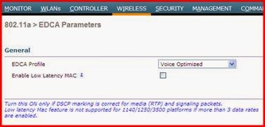
I'll start off with screenshots of the 5GHz (802.11a) global parameters


A number of Wi-Fi clients present in production environments do not actually support connections in the UNII-2 Extended Band. This allotment of channels ranging from 100 to 140 is essentially invisible to older Wi-Fi clients created before this band was made available for Wi-Fi by the FCC.  Since we have many channels to choose from, I'm going to exclude them.


 Now for the screenshots of the 2.4 GHz Global settings… (note 802.11b is turned on)


With the above defaults applied to all WLANs, I used AirMagnet Wi-Fi Analyzer to look at channel one's channel utilization.  This is a snapshot of the CU when five APs are currently set to channel one in a simulated HD Wi-Fi environment in an RF isolated lab.  The APs are in the default AP Group, and there is one client device - my laptop.  The CU is going to change drastically for the better and I'm going to show you how to do just that.


Now let's take a look at what this post is focusing on – the HD Wi-Fi WLAN Profile.  I'm going to focus on the GoHawks 2.4 GHz WLAN since that is the WLAN where we are seeing most of our wireless clients at sporting events.  Here's a screenshot of the most important WLAN when it comes to a basketball game, and a few "before and after" shots as well.  Below is the HD WLAN Profile for 2.4 GHz in the basketball arena.  It has no security, is mapped to a VLAN outside the network and is meant for fast Internet access.  It also has a high channel utilization!


It is tempting to turn on Application Visibility on this WLAN for statistics, but we chose not to.  You can read up on this nifty feature in a previous post of mine.

I'm going to point out that this is the only WLAN we are applying any ACLs to.  We're doing this to cut down on the Bonjour traffic since most of the clients devices in our HD Wi-Fi environment have that feature enabled.

So lets create two ACLs.   Here we go:

Apply those two ACLs to your HD WLAN.

Now here's the "secret sauce" for decreasing that channel untilization and making your HD environment a lot better for your clients.  We're going to use the Cisco's RF Profiles along with the AP Group feature to override those 2.4 GHz default settings.  I'm going to create an RF Profile then an AP group and call it Basketball_seating and lastly, apply it to all of the access points inside the arena.  Keep in mind when you do this, the arena APs all reboot.

Since this post is focusing on HD Wi-Fi, I'm going to concentrate on the basketball's 2.4GHz RF Profile.  Create an RF Profile.  Use a naming convention that makes sense for your environment.  Mine are "RFP" for RF Profile, <name of WLAN> <coverage area> <24=2.4GHz>.  You'll thank me later for this advice.


Here is where we override the 2.4 GHz defaults and disable 802.11b and make our lowest supported 802.11g rate 18 Mbps.


We're using the RRM tab to override the controller's defaults to limit the power thresholds in our basketball arena.


We didn't change anything on these last two tabs.


Now create an AP group for the HD Wi-Fi area.  I cannot stress enough to use a proper naming convention so you can figure out what it is for months from now.


Edit the AP group after it is created, and use a proper description so you can figure out what it is for a few months from now.


AP Groups allow you to only broadcast the WLANs you want.  For the basketball arena we only want to broadcast one WLAN.  If we used the default AP group, we would automatically broadcasts all WLANs.


Then we apply the RF profile we created in the earlier step, overriding the global 802.11b 2.4 GHz parameters.


Use the APs tab to add the arena's access points to the newly created AP Group.  They'll reboot.


After the APs reboot, they come up and I let my AirMagnet Wi-Fi Analyzer run for about ten minutes.  The CU is now down in the single digits!


So, to recap, this is what we did to make our HD Wi-Fi exponentially better.
  1. Replace omnidirectional antennas with directional ones and created small cells
  2. Create ACLs to block Bonjour
  3. Create RF Profiles to limit data rates and transmit power
  4. Create AP groups to limit number of WLANs being broadcasted

Here are a few screenshots from AirMagnet Survey Pro.  These are the coverage patterns from a recent walkabout through the bleachers with directional antennas mounted up high, aiming down at the seats:

This is the walkabout with all 2.4 GHz channels shown.  Notice how we're not getting all the way down to the front seats.  This is because those seats are the farthest from the antennas.


Here's channel one.  The light blue areas are where the signal is strongest, which is where the antennas are mounted.  This walkabout was done when the venue was empty.  This changes when full.


Here's channel six.


Channel eleven:


Here's channel 149.  I decided to show one 5GHz channel just so you could see the coverage pattern differences.  The cell is much smaller than the 2.4GHz channels - but that's fine because we have more 5GHz antennas online than 2.4GHz.  The APs are all dual band, however we shut some of the 2.4GHz radios off.


Please feel free to write to me with any feedback, comments, concerns, or what you did in your HD Wi-Fi environment.

Sunday, February 2, 2014

Cisco 5508 WLAN controller licensing


I recently looked into increasing licensing on three WLAN controllers that are currently licensed for 150 access points each.  The decision was made to add 150 licenses to each controller - however as you can see, the math doesn't work out well after you look at the available part numbers for when placing an order.


I would need add a 50 and a 100 AP license to each controller, so I contacted a vendor for pricing.  I’m not going to mention the vendor – this is just an example of pricing.  The far right column is the extended price I would pay for each.


I was curious as to how much each AP license cost per SKU.


L-LIC-CT5508-25A = $270.44

L-LIC-CT5508-50A = $232.64

L-LIC-CT5508-100A = $175.85


In order for me to add 150 access points to each controller, I would need to spend $29,216.47.  That’s $194.78 per AP license.


I decided to ask around to see if there was a 150 AP SKU, and the conversation ended up going in the direction of “Can I buy a 250 AP adder license and carve it up”?  Nobody seemed to know the answer, so I emailed licensing@cisco.com.  I was told by someone on the licensing team (after providing the serial number of the 5508 controller) that they would carve up a larger license into smaller ones!  Who knew!


Next step was to return to the vendor and ask for pricing for a quantity of two 250-AP licenses.


2x L-LIC-CT5508-250A = $158.50 per AP.


Even if I do the math and divide by 450, which is the number of licenses I actually need, I end up with $176.11 per AP license.


Any way you look at the numbers, it is cheaper to buy bigger licenses and carve them up among your controllers when adding capacity.


At the time of this writing, I have not purchased the licenses mentioned above, which means I have not actually had the licenses carved up.  I do, however, have documentation from the licensing team stating they would do it for me.


Needless to say, I think it is worth the inquiry if you are doing any upgrades on your Cisco 5508 series WLAN controllers.  I would love to see a 500-AP SKU if it turns out to be true!


Saturday, November 30, 2013

Outdoor WLAN site survey


Last year I wrote a blog post because I thought I was going to be doing a lot of outdoor WLAN site surveying.  That post went through all the details of how to set your PC up, step by step, to get you up and running with outdoor surveying.  Fast forward to this month, when we were tasked with designing and installing some outdoor WLAN coverage for a manufacturing plant.


Since the area was not too large, I decided to survey it twice.  The first survey was the regular walkabout – the way you would site survey an indoor area.  As you can see, I went with the default settings for signal propagation on the walkabut – and if I were to do it all over again, I would set it at fifty feet or so.


There are four Cisco 1552 series mesh access points in this design, and they’re not meshed together.  They are all in local mode, which means they are not using backhaul radios – both radios are for client access.  One thing I want to point out is that one is pole mounted, one is mounted to building with wood siding, and the other two mounted to metal skinned buildings.  All four access points have the dynamite stick antennas, too.  Can you tell which ones are which?


I really should have changed the survey propagation when I did this walkabout(above), since it makes it look like we provided coverage inside those buildings.  By the way, those buildings are in the 200,000 – 400,000 square foot range.


By looking at the same survey (below) at -50dBm, you can see where the access points are.  My guess is that you can also make a better guess as to which ones are mounted to metal buildings and which ones are not.


Here’s the same area(below) – the only changes are that I am doing a GPS survey this time, and a few days later.  I’m letting RRM control the power, just like the walkabout survey above.  The power on three of the APs was set at three, and one of them was set to full power – which is where the controller thought they needed to be.  The original site survey was done at power level three for -75dBm 2.4 GHz coverage.  I surveyed it that way because I wanted to see the coverage area that the controller thought I needed.  All of the buildings in this coverage area have Wi-Fi inside them – however the metal skinned buildings tend to block most of the signals from escaping.   I recently did a WLAN survey in a Quonset building (corrugated metal building in the shape of a 55 gallon drum cut in half length-wise) and when we walked out of that building, all signals were blocked entirely.  If I ever need a Faraday cage, I will remember to ask them if I can borrow their building.


Here’s -75dBm 2.4 GHz coverage.  Three APs power level three, one AP power level of one:


After changing the power to level three on the access point that was set to level one (and statically setting the other three so they would not change) I surveyed again.  It’s amazing how your feet don’t get tired when you drive around with a laptop on your dashboard and a GPS receiver taped to the roof of your car.


You might think that dropping the power level on the AP set to power level one would make a big difference in the -75dBm coverage.  Each power level is a 3dB change in the WLAN controller.  Dropping the power level two notches effectively cuts the power in half, and then cuts that power in half again.  The AP that was on full power was the AP closest to the bottom of the screenshot.  I expected something a little more dramatic, actually.  We were aiming to cover that parking lot directly below the access point.  The controller must have thought we wanted to cover both parking lots.  You can see the coverage area decrease slightly in the survey below.


Here’s -75dBm 2.4 GHz coverage.  All APs set to power level one:


All in all, we covered the two parking lots we were aiming to cover, along with the area between the buildings so that WLAN client devices could roam from one building to another when the human did.  One thing to note – see that “main drag” where I drove from the top of the map to the bottom -  the signal seems to drop off immediately for some reason?  That street is lined with very large trees that stay green all year long.  I  could cover it with Wi-Fi, but what’s the point?  You should be looking at those gorgeous trees!


Thursday, November 21, 2013

Upgrading Cisco Prime 1.2 to 3.0

I am writing this for myself and anyone else that might be upgrading your Cisco Prime Infrastructure (PI) in the future.  After doing all the research, I discovered I needed to first patch our PI and make backups.


Not knowing which day I was going to do the upgrade, I decided to configure PI to back itself up daily so I would always have a fresh backup and not have to wait to create one if I decided to the upgrade that day.


I browsed here:  Administration  >  Background Tasks >  Other Background Tasks  >  Prime Infrastructure Server Backup


I created a backup repository and configured it to do daily backups at 03:30 in the morning.


Next step was to copy the patches to PI.  I downloaded these two files from CCO:  pi_1.2.1.12_update.tar.gz  and  PI_1_2_1_12u-Update.1.tar.gz


I figured I would use WinSCP, so I tried to login with the file protocol = SCP and my root credentials and was denied.  Bummer.  Something about an incompatible version.  Next I tried FTP, but now my credentials were not working.  Research showed that I needed to create an FTP account on PI.


I logged in via SSH and created an FTP account.  Here’s how: (FTP Username – “ftpaccount”, password = My8l0gpw0rD


CiscoPI/admin# ncs password ftpuser ftpaccount password My8l0gpw0rD


Initializing...

Updating FTP password.

This may take a few minutes...

Successfully updated location ftp user

CiscoPI/admin#


That was all it took to create the FTP account.  Now I used WinSCP to copy the two patch files to PI from my workstation.


Now that the patches are in PI, verify they are there and then run them.


CiscoPI/admin# show repository localftp

Backup_ciscopi01_130926_010000.lsbackup

Backup_ciscopi01_131001_010000.lsbackup

PI_1_2_1_12u-Update.1.tar.gz

pi_1.2.1.12_update.tar.gz


CiscoPI/admin# patch install PI_1.2.1.12u_update.tar.gz localftp

Save the current ADE-OS running configuration? (yes/no) [yes] ? yes

Generating configuration...

Saved the ADE-OS running configuration to startup successfully

Initiating Application Patch installation...


Patch successfully installed


CiscoPI/admin# patch install pi_1.2.1.12_update.tar.gz localftp

Save the current ADE-OS running configuration? (yes/no) [yes] ? yes

Generating configuration...

Saved the ADE-OS running configuration to startup successfully

Initiating Application Patch installation...


Patch successfully installed

CiscoPI/admin# sh version


Cisco Application Deployment Engine OS Release: 2.0

ADE-OS Build Version: 2.0.1.038

ADE-OS System Architecture: x86_64


Copyright (c) 2005-2010 by Cisco Systems, Inc.

All rights reserved.

Hostname: CiscoPI


Version information of installed applications

---------------------------------------------

Cisco Prime Network Control System

------------------------------------------

Version : 1.2.1.012

Patch: Update for Prime Infrastructure 1.2.0 - backup,restore,upgrade improvements Version: 1.2.1.12

Patch: PI Patch - includes backup, restore and upgrade related updates Version: 1.2.1.13

CiscoPI/admin


A month passed and the decision was made to try an “inline upgrade” – which is basically copying the PI 2.0 software to the virtual machine and executing an upgrade.  We went with this way for a variety of reasons.  I had read that the best was to backup your existing PI, create a new VM with the PI 2.0 OVA and restore your backup into that VM.  I had also read about some inline upgrades that were having disk space issues, but decided to try it anyway.


This time I used the 3CDaemon TFTP/FTP application to FTP the upgrade file to PI.  The application is free, and I have had a much luck with it over the years.   If you haven’t used it, you’ll need to download and install it, and then run the application.  Click on FTP Server and create a username and password – you will need this for PI to login to your FTP server app.


Now log back into your PI via SSH and copy the upgrade file from your FTP application.  Here is a line by line step, with output, comments and commands in red:


copy ftp://10.10.20.50/PI-Upgrade-2.0.0.0.294.tar.gz disk:/defaultRepo

Username: <from FTP app>

Password:  <from FTP app>

<the FTP server is now transferring the upgrade file.  Be patient>

CiscoPI/admin#  


<Verify file is where you told it to go>


CiscoPI/admin# dir disk:/defaultRepot


Directory of disk:/defaultRepo

1700049411 Nov 12 2013 18:01:45  PI-Upgrade-2.0.0.0.294.tar.gz  <Here’s the file you just transferred.  Looks right>


           Usage for disk: filesystem

                74685308928 bytes total used

                42612486144 bytes free

                123677184000 bytes available


<Now shutdown NCS and run the upgrade>


CiscoPI/admin# ncs stop

Stopping Network Control System...

This may take a few minutes...

Network Control System successfully shutdown.

SAM daemon process id does not exist

DA daemon process id does not exist

DA syslog daemon process id does not exist

Stop

<now run the upgrade>

CiscoPI/admin# application upgrade PI-Upgrade-2.0.0.0.294.tar.gz defaultRepo

Save the current ADE-OS running configuration? (yes/no) [yes] ? yes

Generating configuration...

Saved the ADE-OS running configuration to startup successfully

Initiating Application Upgrade...

  Stage 1 of 7: Transferring file ...

  -- complete.

  Stage 2 of 7: Unpacking file ...

  -- complete.

  Stage 3 of 7: Executing pre-install ...


[WARNING] System will reboot after a successful installation of this package (after Stage 7).

After reboot, please login again into the server to check status.

No action required at this time. Continuing with Stage 3.


<These steps took over 12 hours.  Be patient.  I thought it was stuck, so I went home and let it run all night and was pleasantly surprised the next morning>


  -- complete.

  Stage 4 of 7: Upgrading binaries ...

  -- complete.

  Prime Infrastructure Application installation completed


  Stage 5 of 7: Retrieving system version ...

  -- complete.

  Stage 6 of 7: Updating Database Schema ...

              : This could take long time based on the existing data size.

                  Stage 1 of 5: Pre Migration Schema Upgrade ...

                                        -- completed at: 2013-11-12 19:20:50.923

, Time Taken : 0 hr, 5 min, 31 sec

                  Stage 2 of 5: Schema Upgrade ...

                                : This could take long time based on the existing data size.

                                        -- completed at: 2013-11-12 19:43:22.763

, Time Taken : 0 hr, 22 min, 31 sec

                  Stage 3 of 5: Post Migration Schema Upgrade ...

                                        -- completed at: 2013-11-13 01:14:27.926

, Time Taken : 5 hr, 31 min, 5 sec

                  Stage 4 of 5: Enabling DB Constraints ...

                                        -- completed at: 2013-11-13 04:16:54.362

, Time Taken : 3 hr, 2 min, 21 sec

                  Stage 5 of 5: Finishing Up ...

                                        -- completed at: 2013-11-13 04:17:22.815

, Time Taken : 0 hr, 0 min, 28 sec

  -- complete.

  Stage 7 of 7: Re-enabling Database Settings ...

  -- complete.

Upgrade Finished. Server is  restarting . Please wait ..


% This application Install or Upgrade requires reboot, rebooting now...


Broadcast message from root (pts/0) (Wed Nov 13 04:24:36 2013):


The system is going down for reboot NOW!


Application upgrade successful

CiscoPI/admin#


<Now you are finished.  Don’t forget to upgrade your MSE if you have one>


Wednesday, November 20, 2013

Upgrading your MSE (Licenses change)

I am writing this for myself and anyone else that might be upgrading your MSE 3355 in the future.  I found the two documents (links will need CCO account) below, but my varied a little – so here goes.  I went with the first option, since I didn’t require data migration.


http://tools.cisco.com/squish/B7496


http://tools.cisco.com/squish/F1136


Step one was to “back up the existing database using the Prime Infrastructure.”  There was no link or other direction on how to do this, and I didn’t feel the need, so I didn’t do it.  A link to how to do it would have been nice, however.  I believe they wanted you to log into Prime Infrastructure and go here:

Services > Mobility Services Engines > smonmsep01 > System > Maintenance > Backup Operation


Step two and three was Transfer the *.tar file fro 7.4.110.0 to the MSE appliance and place it in the /opt/installers folder.

The step said to use “CISCO-MSE-L-K9-7-4-110-0-64bit.db.tar”. 


I found the file to be named “CISCO-MSE-L-K9-7-4-110-0-64bit.bin.gz” on CCO, which I downloaded.  I used WinSCP to simply and painlessly FTP the file from my desktop to the MSE.  You’ll need the username, password and IP address of your MSE.


Step four was to decompress the file.  I used TeraTerm to SSH into the appliance.


[root@CiscoMSE /]# cd opt


[root@CiscoMSE opt]# ls (next step change to OPT)

data  installers  lsi  MegaRAID  mse  oracle  ORCLfmap


[root@CiscoMSE opt]# cd installers

[root@CiscoMSE installers]# ls

CISCO-MSE-L-K9-7-0-201-204-64bit.bin.gz  database_installer_part2of4.zip

CISCO-MSE-L-K9-7-3-101-0-64bit.bin       database_installer_part3of4.zip

CISCO-MSE-L-K9-7-4-110-0-64bit.bin.gz    database_installer_part4of4.zip

database_installer_part1of4.zip 


The directions stated step four was to “Untar the file: tar -xvf CISCO-MSE-K9-7-4-110-0-64.bit-db.tar”. 

My file was .gz, so I skipped that step and when right to gunzip.


Now we can actually unzip the file with the gunzip command.  


[root@CiscoMSE installers]# gunzip CISCO-MSE-L-K9-7-4-110-0-64bit.bin.gz

[root@CiscoMSE installers]# ls

CISCO-MSE-L-K9-7-0-201-204-64bit.bin.gz  database_installer_part2of4.zip

CISCO-MSE-L-K9-7-3-101-0-64bit.bin       database_installer_part3of4.zip

CISCO-MSE-L-K9-7-4-110-0-64bit.bin       database_installer_part4of4.zip

database_installer_part1of4.zip


Next we change the permissions of the file so we can execute the installation.


[root@CiscoMSE installers]# chmod +x CISCO-MSE-L-K9-7-4-110-0-64bit.bin


Now stop the MSE.


[root@CiscoMSE installers]# service msed stop

Stopping MSE Platform

Shutting down framework and services ...

Shutting down framework and services ....................

Flushing firewall rules: [  OK  ]

Setting chains to policy ACCEPT: nat filter [  OK  ]

Unloading iptables modules: [  OK  ]


The next step was to uninstall the existing MSE software.  There were no directions, links, etc, on how to do it, so I skipped that step and went to the next one, which was “invoke the MSE Installer”.  I will also include the output of the CLI just as a reference.  This took less than a half hour to complete.


[root@CiscoMSE installers]# ./CISCO-MSE-L-K9-7-4-110-0-64bit.bin

Preparing to install...

Extracting the JRE from the installer archive...

Unpacking the JRE...

Extracting the installation resources from the installer archive...

Configuring the installer for this system's environment...


Launching installer...


Preparing CONSOLE Mode Installation...


===============================================================================

Cisco Mobility Services Engine    (created with InstallAnywhere by Macrovision)

===============================================================================

Introduction


InstallAnywhere will guide you through the installation of Cisco Mobility

Services Engine.


It is strongly recommended that you quit all programs before continuing with

this installation.


Respond to each prompt to proceed to the next step in the installation.  If you

want to change something on a previous step, type 'back'.


<read this carefully>


Licensing on the Mobility Services Engine is enforced with the release of

software version 6.x and greater. Please have the Product Authorization Key

(PAK) and refer to the instructions in the User Guide to enable licensing.


PRESS <ENTER> TO CONTINUE:


===============================================================================

Installing MSE version: 7.4.110.0

===============================================================================

Installation Check

------------------

The system appears to have a Cisco Mobility Services Engine already installed.

If you choose "Continue", all the currently installed components will be

removed permanently (Only database and license files will be preserved).


  ->1- Exit

    2- Continue


ENTER THE NUMBER OF THE DESIRED CHOICE, OR PRESS <ENTER> TO ACCEPT THE

   DEFAULT: 2

===============================================================================

Current Role - Primary

----------------------


High Availability Role is currently set to Primary from previous installation.


If need to change role to Secondary or re-configure high availability settings,

please execute setup.sh after installation is completed.


PRESS <ENTER> TO CONTINUE:


===============================================================================

MSE Startup

-----------


Would you like the Cisco Mobility Services Engine to startup automatically at

system boot up?


  ->1- Yes

    2- No


ENTER THE NUMBER OF THE DESIRED CHOICE, OR PRESS <ENTER> TO ACCEPT THE

   DEFAULT: 1


===============================================================================

Pre-Installation Summary

------------------------


Please Review the Following Before Continuing:


Product Name:

    Cisco Mobility Services Engine


Install Folder:

    /opt/mse


Link Folder:

    /tmp


Disk Space Information (for Installation Target):

    Required:  2,570,778,828 bytes

    Available: 497,276,530,688 bytes


PRESS <ENTER> TO CONTINUE:


===============================================================================

Installing...


[==================|==================|==================|==================]

[------------------|------------------|------------------|------------------]


===============================================================================

Database Installation


The installer will now install the database. This may take a long time (up to

30 minutes). Do not cancel the installer.


PRESS <ENTER> TO CONTINUE:


===============================================================================

!!!! IMPORTANT NOTE !!!! :

--------------------------


The system is minimally configured right now. It is strongly recommended that

you run the setup script under /opt/mse/setup/setup.sh to configure all

appliance related parameters immediately after installation is complete.


The hostname must be set correctly on the system. The Cisco MSE platform will

NOT start if it is configured incorrectly or not configured at all.


Additionally, it is strongly recommended that the Cisco MSE be configured to

use the same NTP servers as the controllers with which it will be synchronized.

This is essential to the correct operation of the Cisco Mobility Services

Engine.


Both these parameters may be configured as part of the setup script.


PRESS <ENTER> TO CONTINUE:


===============================================================================

Installation Complete

---------------------


Congratulations. Cisco Mobility Services Engine has been successfully installed

to:


/opt/mse


Licensing on the Mobility Services Engine is enforced with the release of

software version 6.x and greater. Please have the Product Authorization Key

(PAK) and refer to the instructions in the User Guide to enable licensing.


PRESS <ENTER> TO EXIT THE INSTALLER: [root@CiscoMSE installers]#


Just a note about this:  I didn’t see the MSE come back to life.  I had to restart the service.  Command is “service msed start”


[root@CiscoMSE /]# service msed start


Starting MSE Platform


Flushing firewall rules:                                   [  OK  ]

Setting chains to policy ACCEPT: filter                    [  OK  ]

Unloading iptables modules:                                [  OK  ]

Starting Health Monitor, Waiting to check the status.

Health Monitor successfully started

Starting Admin process...

Started Admin process.

Starting database ....

Database started successfully. Starting framework and services .................

Framework and services successfully started

[root@CiscoMSE /]#


Now to check with Prime Infrastructure – which was just upgraded to 2.0 several days ago. (the reason for this upgrade)


Here’s a screenshot from this link:


http://www.cisco.com/en/US/docs/wireless/mse/3350/release/notes/mse_7_4_110_0.html#wp1233900


Saturday, November 2, 2013

How to block Bit torrent on your WLAN

I came across an interesting feature I would like share on the 7.4 version of Cisco 5508 WLAN controller.


I was asked to block bit torrent, audio and voice streaming on the guest WLAN for obvious reasons.  The old way, doing it on a firewall or with an ACL on the WLAN controller was rather clunky at best.


If you are either on 7.4 or can jump to it, here’s all it took to turn on this nifty feature.


Here’s the flavor of code that I’m running:


Browse to Wirelessà Application Visibility And Control à AVC Profiles and select NEW.


Next come up with a name that fits your organization.  I’ll call mine “WLAN Restrictions” because there will be a list of things and not one single application.  Your mileage may vary, of course.


After you create the Profile, click on it and you will see that there are no rules associated with the profile.


Look over to the right hand side of the screen and click on “Add New Rule”…


This way is kind of clunky, but I will go ahead with explaining it.  To block Audio, you have to select “voice-and-video” as the Application Group and then select the Application Name.  In this case, I selected “audio-over-http” and then selected Drop as the action.


Now you can add another rule.  But this time we’re going to go a different way.  We want to block bit torrent, but we don’t know which Application Group it is in.  This time, browse to Wirelessà Application Visibility And Control à AVC Profiles and select AVC Applications.


This time,


Scroll down and click “bittorrent” and then use the AVC Name Drop down and select the Application Profile you created in the first step and select Ddrop as the action.  Drop is the default, so you really don’t have to do anything.


Now browse to the WLAN you want to apply the AVC Profile to.  I’m sure you know where it is, but in case you forgot, browse to WLANSà WLANsà WLAN ID (of the WLAN Profile) and then browse to the QoS tab.  Select the AVC Profile and apply.


That’s it.  You’re finished.  Don’t forget to save your config! 


Wednesday, August 14, 2013

Wall mounting vs. Ceiling mounting your access points

This post stems from the knowledge of how to properly mount your access points.  I recently went to do a validation survey for a 5 GHz WLAN, and discovered two of the three access points were mounted on the wall, perpendicular to the floor.


I decided to survey it anyway, and then remount the access points another day when I had the appropriate hardware, and re-survey.  I wanted to see what the actual coverage pattern would be – a “before and after”, if you would like to think of it that way.


Here is the coverage of the floor before making any changes.  The green and purple coverage patterns are created by two access points mounted “incorrectly”.  They’re both hanging like wall clocks, instead of being mounted on the ceiling like UFOs.  The brick colored pattern is mounted horizontally, and no change was made to this access point.


Here is the overlapping coverage in red.


I remounted the green access point horizontally about 3 feet from the telepole where it had been mounted vertically.  The “purple AP” I had to move from the hallway into the room next to the stairwell since there was no ceiling or structure to mount it to in the hallway. 


This is the “after” overlapping coverage area.


I must admit that I expected something a little more dramatic.  I used the same laptop, the same adapter, and walked the same path on both surveys.


I’m interested if anyone else has done any comparison surveys like this, what did they show?